Evolving Vertically


- © 2018 Steve Allen Contact Me 0
(This text duplicated on Horizontal Evolution page)
All steam engines have a forward and reverse direction. It is usually possible to to determine by examining the design of the crosshead. When running, a steam engine converts a reciprocating action into a rotary action. The crosshead is at the intersection of these two movements. In converting this direction of movement a sideways force is imparted on the crosshead. To counter this a bearing surface is machined to support the crosshead and prevent it from deviating from its reciprocating movement. In full size Horizontal engines this bearing surface is enough as gravity maintains the crosshead in contact with the bearing surface. In vertical engines some form of guide is normally provided opposite the bearing surface. These guides also have bearing surfaces but of much smaller area as they are primarily to prevent crosshead slap at the end of stroke when lateral force is quickly reduced to zero before being reapplied. In the forward direction all the lateral movement is resisted by the large bearing surface. In reverse however the lateral force is resisted by the much small guide bearing surfaces, allowing lateral movement of the crosshead however small. This can lead the metal fatigue and excessive wear. So to determine the forward direction look to see which rotational direction applies lateral forces against the main crosshead bearing. This asymmetry in power capability is not normally an issues as many engines only run in one direction. For those that do reverse like Marine engines full power is only required in one direction whilst reverse is restricted to a small fraction of that and for limited duration. This whole idea of forward direction is I believe widely misunderstood as many engines I see are running in reverse. I recently purchased a large Stuart turner engine that I believe to be a factory machined or factory assembled. The timing is so perfect the engine runs as smooth as any i have seen, but in reverse. In slow motion you can see the crosshead slap at the extreme end of travel.
So what if you need an engine that can run equally powerfully in both directions? You design it with equally substantial bearing surfaces on both sides of the crosshead. By having equal support for the crosshead you effectively can call either direction forward or reverse, it doesn't matter. Over the years Stuart Turner has changed the designs of many engines whilst retaining the series number or sufixing with a letter. There have been 3 basic variations in vertical engines and 2 in horizontal engines. Not all engines have gone through the complete set as it were so I have chosen the No.7 as an example of vertical engines and the No.8 of horizontal.
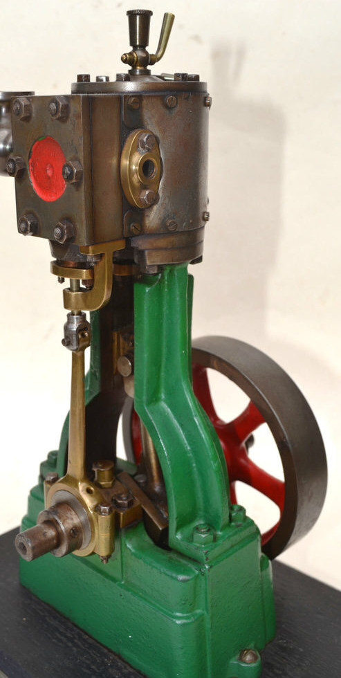
The Original Layout of Standard and rod is cheaper in materials and easy to machine and faily easy to set up. The limit of crosshead support on one side enable single direction only use for maximum power or for any duration. The design can withstand a certain amount of cumulative inaccuracy. By machining all the structural parts except the rod, assembly of the engine allow the rod to be machined to account for any cumulative errors. I have come accross engines where the rod is machined so that a small collar at the top takes correctly aligns the engine. ( its easier to machine a small part accurately than a large part)
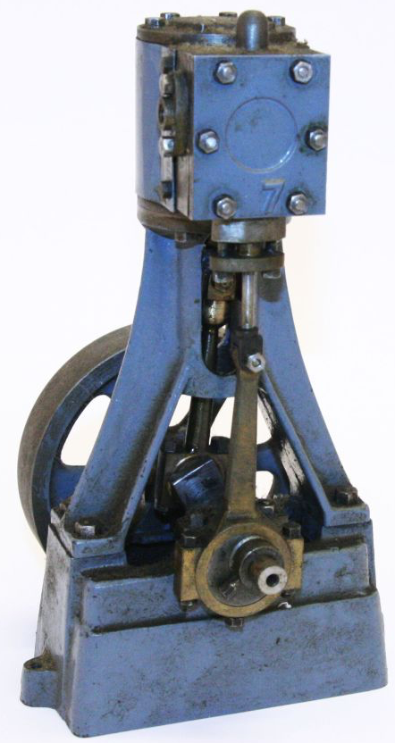
To improve the design for full reverse operation the least effort method is to go for Dual Standards. This utilizes a second Standard the same as the first. With this design the two standards must be machined with greater accuracy and any dimensional differences will upset the geometry of the engine, for example causing the crosshead to not move in line with the piston perhaps bending the piston rod. When machining duplite parts like this is usual to not fully machine one part and then the other but instead to perform one machining element on part A then duplicate that on part B with the lathe or mill still setup, before machining the second element and duplicating. Equally some machining elements may be held back until assembly , for example the crosshead may be machined after the standards have been assembled to the soleplate and cylinder block so as to ensure that its width accurately fits the machined bearing surfaces on both standards. (A common find on these engines is oval holes for the mounting studs so that alignment of the standards can be fiddled to aling correctly. I sometimes find holes filled and redrilled.)
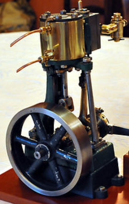
The Third option Stuart chose was the Trunk standard, this takes the form of an inverted "Y" with a tubular machined crosshead guide in the to. This design makes machining a lot simpler as only one standard needs to be machined. Machining the round croshead guide and crosshead are much easier to machine accurately that two pairs of bearing surfaces. The construction is simpler and more structularly sound as well as being lighter in weight.
It can be seen that the change from Standard & Rod to Dual Standard was made with minimal exra effort in change to design as the priority. The second change from Dual Standard to Trunk Standard was made with effectiveness and simplicity as the priority. These design choices were probably the same used by steam engine designers back in the days of STEAM and ites evolution of design.
Some of my suggestions regarding machining operations or oder of machining come from my experience taking previously machined engines and correcting them to work properly by re-maching or replacing parts. When maching an engine from the start I decide on an order that allows for a certain amount of handbuilt rather than machineing all parts and then assembling. Adjacent or interacting parts tend to be machined in conjunction or at the same time. I have a Nice Stuart Triple Marine engine purchased uncompleted. The level of machining is excellent up to the point when the engineer drilled the holes for mounting the valve chests for the end cylinders. The valve chest and covers are drilled exactly to the drawings specification but the holes in the cylinder block have broken through the bottom edge of the casting. The Cylinder block has been machined so that it is not as tall as the drawings. So when the valve chest was aligned at the top and the matching holes were drilled, the bottom ones were too close to the bottom edge of the casting. The reason i haven't completed it is that i am in two minds as to how i sort the problem out. Fill the holes in the cylinder block and remachine the valve chests and cover to a new bolt pattern or to machine a new block. The issue of piston travel being to great for the cylinder block height could be sorted by shaving the pistons but I managed to obtain a very nice set of Bulged cylinder top covers that look so much better than the flat, current Stuart ones. I also have a new machined cylinder block but the intermediate cylinder steam ports need machining and I have always hated that job.

Please Consider Making a Donation